|
|
|
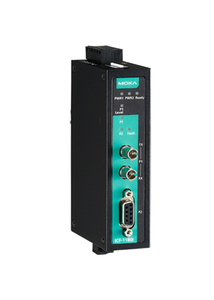
Moxa ICF-1180I-M-ST-T - Industrial PROFIBUS to Fiber Optic Converter, ST Multi-mode, -40 to 75 Degree C
by MOXA
|
|
|
|
- Fiber cable test function validates fiber communication
- Auto baudrate detection and data speed up to 12 Mbps
- PROFIBUS bus fail prevents corrupted datagram in functioning segment
- Fiber inverse feature
- Alarm by relay output
- 2 kV galvanic isolation protection
- Dual power inputs for redundancy (Reverse power protection)
- Extends PROFIBUS transmission distance up to 45 km
- Wide temperature model available for -40 to 75°C environments
Supports Fiber Signal Intensity Diagnosis
|
|
|
Overview
The ICF-1180I series industrial PROFIBUS-to-fiber converters are used to convert PROFIBUS signals from copper to optical fiber. The converters are used to extend serial transmission up to 4 km (multi-mode fiber) or up to 45 km (single-mode fiber). The ICF-1180I
provides 2 kV isolation protection for the PROFIBUS system and dual power inputs to ensure that your PROFIBUS device will perform uninterrupted.
Fiber Cable Test Function
Fiber-optic cables are usually deployed for long distance communication. To ensure proper communication across the fiber-optic cables, engineers use fiber sensors. With fiber cable test function through DIP switch adjustments, the ICF-1180I series converters eliminate the need to rely on fiber-optic sensors. This function not only detects fiber communication abnormalities but also validates the format of the received packet. It can also determine which side (Tx or Rx) is causing the problem.
PROFIBUS Fail Safe
.jpg) When the PROFIBUS device malfunctions or the serial interface fails, it will generate electrical noise, resulting in bus failure. Traditional media converters will let the noise signal pass through the fiber and on to the other converter. This will disrupt data transmissions between the two buses and eventually communication ceases across the entire system. When this occurs, the engineer will not be able to easily locate the failed device because the entire PROFIBUS network is down. To avoid this situation, the ICF-1180I was designed to detect and recognize noise signals. If the bus fails on one side, the noise signal will not propagate through the ICF-1180I and affect additional bus segments. In addition, the ICF-1180I will also trigger an alarm notification to the field engineer on the location of the failure. When the PROFIBUS device malfunctions or the serial interface fails, it will generate electrical noise, resulting in bus failure. Traditional media converters will let the noise signal pass through the fiber and on to the other converter. This will disrupt data transmissions between the two buses and eventually communication ceases across the entire system. When this occurs, the engineer will not be able to easily locate the failed device because the entire PROFIBUS network is down. To avoid this situation, the ICF-1180I was designed to detect and recognize noise signals. If the bus fails on one side, the noise signal will not propagate through the ICF-1180I and affect additional bus segments. In addition, the ICF-1180I will also trigger an alarm notification to the field engineer on the location of the failure.
Fiber Signal Intensity Diagnosis
In some circumstances, you may need to measure the receive level of the fiber optic port with a voltmeter, which can be connected while the device is operating (doing so will not affect data transmission). The measurement can be taken with a voltmeter and read on a PLC that uses floating high impedance analog inputs, which allows you to do the following: 1. Record the incoming optical power for later measurement (e.g., to indicate aging or damage). 2. Carry out a good/bad test (limit value).
| • Technology |
| Standards |
IEC 61158-2 for PROFIBUS DP |
| • Interface |
| P1 Port |
ST optical fiber |
| P2 Port |
PROFIBUS DP (DB9 female) |
| Relay Alarm |
One relay output with current carrying capacity of 2 A @ 30 VDC (Normal open) |
| LED Indicators |
PWR1, PWR2, Ready, P1 Status, P2 Status |
| DIP Switches |
DIP 1 to 4: Baudrate setting
DIP 5: Fiber link monitor
DIP 6: Fiber inverse function
DIP 7: Reserved
DIP 8: Fiber cable test function |
| • PROFIBUS Communication |
| Data Rate |
9.6, 19.2, 45.45, 93.75, 187.5, 500, 1500, 3000, 6000, and 12000 kbps |
| Auto Baudrate |
Yes |
| Isolation Protection |
2 kV |
| • Optical Fiber Side |
| Point-to-Point Transmission |
.jpg) |
| • Physical Characteristics |
| Housing |
Metal |
| Mounting |
DIN-Rail mounting, wall mounting (with optional kit) |
| Dimensions |
30.3 x 115 x 70 mm (1.19 x 4.53 x 2.76 in) |
| Weight |
180 g |
| • Environmental Limits |
| Operating Temperature |
Standard Models: 0 to 60°C (32 to 140°F)
Wide Temp. Models: -40 to 75°C (-40 to 167°F) |
| Storage Temperature |
-40 to 75°C (-40 to 167°F) |
| Ambient Relative Humidity |
5 to 95% (non-condensing) |
| • Power Requirements |
| Input Voltage |
12 to 48 VDC |
| Power Consumption |
186 mA @ 12 V |
| Connector |
Terminal Block |
| Power Line Protection |
Level 3 (2 kV) Surge Protection |
| Over Current Protection |
1.1 A |
| • Standards and Certifications |
| Safety |
UL 508, EN 60950-1 |
| Hazardous Location |
UL/cUL Class I Division 2 Groups A/B/C/D, ATEX Zone 2 EEx nC IIC, IECEx |
| EMC |
CE, FCC Part 15 Subpart B Class A |
| EMI |
EN 55022, Class A; EN 55024 |
| EMS |
EN 61000-4-2 (ESD) Level 3,
EN 61000-4-3 (RS) Level 3,
EN 61000-4-4 (EFT) Level 3,
EN 61000-4-5 (Power Surge) Level 3,
EN 61000-4-5 (Communication Surge) Level 3,
EN 61000-4-6 (CS) Level 3 |
| Green Product |
RoHS, CRoHS, WEEE |
| Freefall |
IEC 60068-2-32 |
|
|
|
|