|
|
|
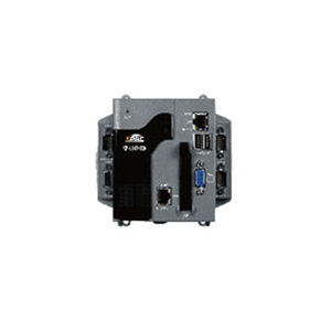
ICP DAS 3 slot base, Windows CE 6.0, ISaGRAF Programmable Controller, 520 Mhz CPU, 1 GB RAM, and 4 GB Flash Disk, VGA Port, 10 /
by ICP DAS
|
|
|
|
Programmable Automation Controller with ISaGRAF and Windows Embedded CE 6.0 operating system. Communicates over USB, Ethernet, VGA, RS-232 and RS-485. Supports Modbus TCP/IP and Modbus RTU protocol.
|
|
|
Features
The XP-8x47-CE6 (XP-8047-CE6, XP-8347-CE6, XP-8747-CE6, XP-8047-CE6-PRO, XP-8347-CE6-PRO and XP-8747-CE6-PRO) is the new generation of ICP DAS ISaGRAF Programmable Automation Controller (PAC). It is equipped with an AMD LX 800 CPU (500 MHz) running a Windows Embedded CE 6.0 operating system, and with IsaGraf inside. It supports various connectivity including VGA ports, 2 USB 2.0 ports, 2 10/100 Mbps Ethernet ports, 4 or 5 RS-232/RS-485 ports, and 3/7 slots for high performance parallel-type I/O modules I-8K series and serial-type I/O modules I-87K series, etc. Besides all the features the XP-8x47-CE6 has, the professional version XPAC XP-8x47-CE6-PRO also provides built-in Internet Explorer Software.
Major advantages compared with the WP-8xx7 and VP-2xW7 :
- The USB-mouse operations and Ethernet communication of the XP-8xx7-CE6 are more effective (consume less CPU loading) than the WP-8xx7 and VP-2xW7.
- The memory size (Flash and SDRAM) of the XP-8xx7-CE6 is much more than the WP-8xx7 and VP-2xW7.
- The XPAC Series XP-8xx7-CE6 supports ISaGRAF Ver. 3 Workbench:
- IEC 61131-3 Standard Open PLC Programming Languages (LD, FBD, SFC, ST, IL, FC) + Flow Chart (FC)
- Auto-Scan I/O
- On-Line Debugging/Control/Monitoring, Off-Line Simulation
- Simple Graphic HMI
Hot Features
| Redundant Communication System |
| |
 |
| |
| Modbus TCP/IP Master |
| Each XP-8xx7-CE6, WP-8xx7 or VP-25W7/23W7 supports to link to max. 100 Modbus TCP/IP slave devices. |
| Support various Standard Modbus TCP/IP Slave devices. |
| |
 |
| |
| ZigBee Wireless Solution |
ISaGRAF PAC plus ZB-2550P and ZB-2551P (ZigBee to RS-232/485 Converters) can apply wireless communication, reduce the
wiring cost, and achieve the mission of remote I/O control and data acquisition. |
| |
 |
| |
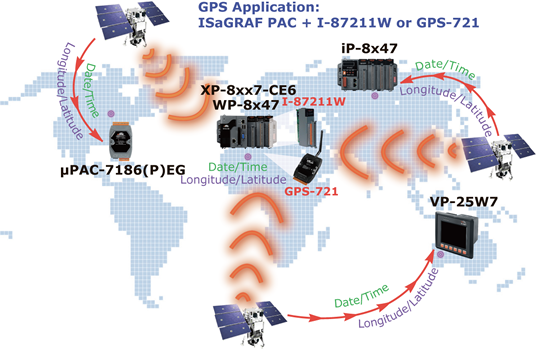
| GPS Applications: ISaGRAF PAC plus I-87211W or GPS-721 |
| XP-8xx7-CE6 can support one I-87211W (slot 1~7) or I-87211W/GPS-721 as RS-485 remote GPS I/O. |
| For doing auto-time-synchronization and getting local Longitude and Latitude. |
| |
 |
| |
| Stress Monitoring Application of Constructions |
ICP DAS releases effective VW sensor solution (Vibration Wire solution). It is useful for measuring the stress of constructions
like building, bridge, dam, etc. |
| This solution has been successfully applied in some water dams monitoring system near the city Wuhan in China. |
| |
 |
| |
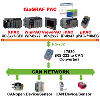
| Integrate with CAN/CANopen Devices and Sensors |
| XP-8xx7-CE6 support max. 32 I-7530 (RS-232 to CAN) Converters. |
| |
 |
| |
| Send Email with One Attached File |
| |
 |
| |
| Data Acquisition and Auto-Report System |
| VC++ 6.0, VB 6.0 and ISaGRAF demo programs are available. |
The XP-8xx7-CE6 can use UDP/IP Client protocol to auto-report acquisition data & control data to local or to remote
Internet PC/Server. |
| |
| Advantage: Every XPAC in the different location doesn't need a fixed Internet IP. |
| |
|
| |
| Modbus RTU/TCP Slave Ports |
| Modbus RTU (RS-232/485/422) Slave : max. 9 Modbus RTU Slave ports. |
| Modbus TCP/IP Slave : max. 64 PC/HMI/SCADA connections. |
| |
 |
| |
| Modbus RTU/ASCII Master Ports |
Modbus RTU/ASCII (RS-232/485/422): max. 33 ports.
(COM1 ~ COM5 and COM6 ~ COM33 if I-8112iW/8114W/8114iW/8142iW/8144iW in Slot 1 ~ 7) |
Only XP-8047-CE6 can use COM1 as Modbus Master port.
| XP-8347-CE6/XP-8747-CE6's COM1 is for internal communication with I-87K modules in slots only. |
| XP-8xx7-CE6 can link to Modbus PLC or M-7000 I/O or Modbus devices (Power meter, temperature controller, inverter etc.) |
| |
|
| |
| Remote I/O Modules |
There are about 100 choices of Local I/O boards ( I-8K, I-87K ) and Remote I/O modules ( I-7K, M-7K and RU-87P1/2/4/8 +
I-87K High Profile cards ). |
| |
 |
RU-87Pn Features |
|
| |
Auto-Configuration - Configurations of I-87K I/O modules can be pre-configured and stored in the nonvolatile memory of the RU-87Pn. |
|
| |
Easy Duplicate System - Using the DCON Utility, you can easily make a backup of the I-87K module configurations and write to another RU-87Pn. |
|
| |
Full Software Support - The free-of-charge software utility and development kits are included. |
|
| |
|
| |
| FRnet I/O |
Fast I/O scan: About 3 ms per FRnet scan. (This depends on your ISaGRAF PLC program's scan time, if the ISaGRAF PLC scan
time is 9 ms, then the scan time for all will be 9 ms, instead of 3 ms.) |
The max. I/O channel number can be 7 x 256 = 1792 Ch. of Digital Inputs plus 1792 Ch. of Digital Outputs. (if all 7 slots are
plug-in I-8172W). |
| Note: Doesn't support FRnet AI/AO modules yet. |
| |
 |
| |
| New Redundant System with Ethernet I/O |
If one Ethernet cable is broken or damaged, the other one will still handle the Ethernet I/O and exchange data with the other
redundant controller. |
| The scan of Ethernet I/O is much faster than that of RS-485 I-7000 or I-87K I/O. |
| |
 |
| |
| New Hot-Swap and Redundant System |
| If one Ethernet cable is broken or damaged, the other one will still work. |
| If one controller is dead, the other one will take over the control of the RS-485 I/O. |
| PC/HMI can connect to this redundant system by one or two active IP. |
| |
 |
| |
| Web HMI |
| The XP-8xx7-CE6-PRO can run its own Internet Explorer to monitor or control the local or remote I/O modules. |
| The XP-8xx7-CE6 require running Internet Explorer in PC to monitor or control the local or remote I/O modules. |
| |
 |
| |
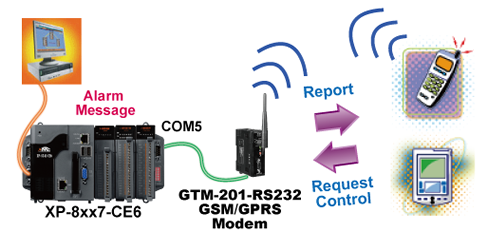
| SMS: Short Message Service |
The ISaGRAF PACs can integrate with a GSM Modem to support SMS: Short Message Service. This allows user to request
information or perform control tasks for the ISaGRAF PAC via his personal cellular phone. In addition, the controller can also
send information and alarms to user's cellular phone. |
| The short message can be sent in multiple language format (like Chinese, English, ...... others). |
| |
 |
| |
| Motion Control |
| One I-8091W can control 2-axis: X-Y plane, or 2 independent axes. |
| Two I-8091W can control 4-axis: X-Y plane + 2 independent axes or 4 independent axes. |
| Encoder Modules I-8093W : 3-axis (FAQ-112) ; I-8084W: 4-axis, without Z-index (FAQ-100) ; I-8090W: 3-axis |
| |
|
| |
| Data Log |
Data, date & time can be stored in Flash Disk or CF card, and then PC can load these data by FTP or Web HMI. |
| |
|
|
| |
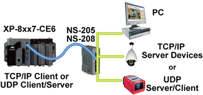
| Communicate with Other TCP/IP Server Devices or UDP Devices |
|
| Models |
XP-8047-CE6
XP-8047-CE6-Pro |
XP-8347-CE6
XP-8347-CE6-Pro |
XP-8747-CE6
XP-8747-CE6-Pro |
| System Software |
| OS |
Microsoft Windows Embedded CE 6.0 |
| .NET Compact Framework |
3.5 |
| Embedded Service |
FTP server, Web server (for all XP-8xx7-CE6)
Internet Explorer (only for XP-8xx7-CE6-PRO version) |
| Development Software |
| ISaGRAF Software |
ISaGRAF Version 3 : IEC 61131-3 standard. Languages: LD, ST, FBD, SFC, IL & FC |
| Max. Code Size |
Accepts max. 2 MB ISaGRAF code size (Appli.x8m must < 2 MB) |
| Non-ISaGRAF |
Options: Microsoft EVC++4.0 or VS .NET 2003/2005/2008 (VB .NET 2003/2005/2008, C# .NET 2003/2005/2008) with .Net Compact Framework 3.5 |
| Web Service |
| Web HMI |
Support Web HMI function, PC running Internet Explorer can access to the XP-8xx7-CE6 via Local Ethernet, Internet or dial Modem to monitoring and control. |
| Security |
Web HMI supports three levels user name and password protection (high/middle/low) |
| Power Supply |
| Input Range |
+10 ~ +30 VDC (unregulated), |
| Isolated |
1 kV |
| Redundant Power Inputs |
Yes, with one power relay (1 A @ 24 VDC) for alarm |
| Capacity |
1.8 A, 5 V supply to CPU
and backplane; total 8 W |
1.8 A, 5 V supply to CPU and backplane; 5.2 A, 5 V supply to I/O expansion slots, total 35 W |
2.0 A, 5 V supply to CPU and backplane; 5.0 A, 5 V supply to I/O expansion slots, total 35 W |
| Power Consumption |
14.4 W (0.6 A @ 24 VDC); |
14.4 W (0.6 A @ 24 VDC); |
16.8 W (0.7 A @ 24 VDC); |
| General Environment |
| Temperature |
Operating: -25 ~ +75 °C,
Storage : -30 ~ +85 °C |
| Humidity |
5 ~ 90 % RH (non-condensing ) |
| System |
| CPU |
AMD LX 800 (32-bit & 500 MHz) processor or compatible |
| System Memory |
512 MB DDR SDRAM |
| Dual Battery Backup SRAM |
512 KB (for 5 years data retention while power off) |
| FLASH |
4 GB as IDE Master |
| EEPROM |
16 KB, Data retention: 40 years. 1,000,000 erase/write cycles |
| CF Card |
1 GB (support up to 32 GB) |
| Hardware Serial Number |
Yes,64-bit hardware unique serial number |
| RTC (Real Time Clock) |
Provide second, minute, hour, date, day of week, month, year |
| Dual Watchdog Timers |
Yes |
| Rotary Switch |
Yes (0~9) |
| DIP Switch |
- |
Yes (8 bits DIP Switch) |
| NET ID |
1 ~ 255, User-assigned by software |
| VGA & Communication Interface |
| VGA Port |
Yes (resolution: 640 x 480, 800 x 600, 1024 x 768,1152 x 864 and 1280 x 1024) |
| USB 2.0 |
2 |
| Ethernet |
RJ-45 x 2, 10/100 Base-TX (Auto-negotiating, Auto MDI/MDI-X, LED indicators)
Please use NS-205/NS-208 Industrial Ethernet Switch. |
| COM1 |
RS-232 (RxD, TxD, and GND);
Non-Isolated; |
Internal communication with the I-87K High Profile modules in slots |
| COM2 |
RS-232 (RxD, TxD, and GND); Non-Isolated; Baudrate: Max. 115200 bps |
| COM3 |
RS-485 (D2+, D2-); self-tuner ASIC inside; Isolated (3000 VDC) |
| COM4 |
RS-232/RS-485 (RxD, TxD, CTS, RTS and GND for RS-232, DATA+ and DATA- for RS-485);
Non-Isolated; Baudrate: Max. 115200 bps |
| COM5 |
RS-232 (RxD, TxD, CTS, RTS, DSR, DTR, CD, RI and GND); Non-Isolated; Baudrate: Max. 115200 bps |
| I/O Slots |
| Slot Number |
0 slot |
3 slots (slot 1 ~ 3) |
7 slots (slot 1 ~ 7) |
| Hot Swap |
- |
* For High Profile I-87K modules only |
| Mechanical |
| Dimensions (W x L x H) |
137 mm x 132 mm x 125 mm |
231 mm x 132 mm x 125 mm |
355 mm x 132 mm x 125 mm |
| Installation |
DIN-Rail or Wall Mounting |
| Motion |
| Motion Control |
- |
Integrate with one I-8091W (2-axis) or two I-8091W (4-axis) |
| PWM Output |
| High Speed PWM Module |
I-8088W, 8-ch PWM outputs, 10Hz ~ 500 KHz (non-continuous), duty: 0.1 ~ 99.9% |
| DO Module as PWM |
8-ch. max. 250 Hz max. For Off=2 & On=2 ms . Output square wave: Off: 2 ~ 32766 ms, On: 2 ~ 32766 ms. Optional DO Boards: I-8037W, 8041W, 8041AW, 8042W, 8050W, 8054W, 8055W, 8056W, 8057W, 8060W, 8063W, 8064W, 8068W, 8069W. (Relay Output boards cannot generate fast square wave) |
| Counter, Encoder, Frequency |
| Parallel DI Counter |
8-ch. max. For 1 controller. Counter val: 32-bit. 250 Hz max. Min. ON & OFF width must > 2 ms. Optional DI boards: I-8040W, 8040PW, 8042W, 8046W, 8048W, 8050W, 8051W, 8052W, 8053W, 8053PW, 8054W, 8055W, 8058W, 8063W. |
| Serial DI Counter |
Counter input: 100 Hz max. Counter value: 0 ~ 65535 (16-bit)
Optional serial I-87K DI boards: I-87040W, 87046W, 87051W, 87052W, 87053W, 87053W-A5, 87054W, 87055W, 87058W, 87059W, 87063W. |
| Remote DI Counter |
All remote I-7000 & I-87K DI modules support counters. 100 Hz max. value: 0 ~ 65535 |
| High Speed Counter |
I-87082W: 100 kHz max. 32 bit; I-8084W : 250 kHz max. 32 bit |
| Encoder |
I-8093W : 3-axis Encoder Module, max. 1M Hz for quadrant input mode, max. 4M Hz for pulse/direction and cw/ccw input mode.
I-8084W: 250 kHz max., 4-ch encoder, can be pulse/direction, or Up/Down or A/B phase (Quad. mode); Not support Encoder Z-index. |
| Frequency |
I-87082W: 2-ch, 1 Hz ~ 100 kHz; I-8084W : 8-ch, 1 Hz ~ 250 kHz; |
| Protocols |
| Modbus TCP/IP Master |
Link to max. 100 devices that support Standard Modbus TCP/IP Slave protocol |
Modbus RTU/ASCII Master
(multi-port) |
Max. 33 COM Ports (COM1~ 5 and COM6 ~ COM33 if multi-serial port boards are plugged in Slot 1~7) can support multi-ports of Modbus RTU/ASCII Master protocol to connect to other Modbus Slave devices. (XP-8347-CE6/8747-CE6's COM1 is for internal communication with I-87K modules in slots only.) |
| Modbus RTU Slave Protocol |
Max. 9 COM Ports (COM1 ~ 33) can support Modbus RTU Slave protocol for connecting ISaGRAF, PC/HMI/OPC Server & HMI panels. (XP-8347-CE6/8747-CE6's COM1 is for internal communication with I-87K modules in slots only.) |
| Modbus TCP/IP Slave Protocol |
2 Ethernet Ports all support Modbus TCP/IP Slave protocol for connecting ISaGRAF & PC/HMI. 2 Ports support up to 64connections. (If PAC uses 1 connection to connect each PC/HMI, it can connect up to 64 PC/HMI; If PAC uses 2 connections to connect each PC/HMI, it can connect up to 32 PC/HMI; ...) When one Ethernet port is broken, the other one can still connect to PC/HMI. |
| Web HMI Protocol |
Ethernet port for connecting PC running Internet Explorer. |
I-7000 & I-87K RS-485
Remote I/O |
One of COM3, COM4 supports I-7000 I/O modules, I-87K base + I-87K Serial I/O boards and
RU-87P1/2/4/8 + I-87K High Profile I/O boards as Remote I/O. Max. 255 pcs. of I-7000/87K Remote I/O modules for one PAC. |
| M-7000 Series Modbus I/O |
Max. 33 RS-485 ports (COM1 ~ 5 & COM6 ~ COM33 if multi-serial port boards are plugged in) can support M-7000 series Modbus I/O. Each port can connect up to 32 M-7000 Modules. (XP-8347-CE6/8747-CE6's COM1 is for internal communication with I-87K modules in slots only.) |
| Modbus TCP/IP I/O |
LAN2 supports ICP DAS Ethernet I/O : I-8KE4-MTCP and I-8KE8-MTCP If LAN2 is broken, it will switch to LAN1 automatically to continuously work. (This need LAN1 & LAN2's IP are set in the same IP domain) |
| FRnet I/O |
Support max. 7 pcs. I-8172W boards in slot 1 ~ 7 to connect to FRnet I/O modules, like FR-2053, FR-2057 FR-32R, FR-32P. Each I-8172W board can connect up to 256 DI plus 256 DO channels. |
| Send Email |
Supports mail_snd and mail_set functions to send email with one attached file via Ethernet port. |
| Ebus |
To exchange data between ICP DAS's ISaGRAF Ethernet controllers via Ethernet port.
(LAN2 Port only) |
| SMS: Short Message Service |
COM4 or COM5 can link to a GSM Modem to support SMS. User can request data/control the controller by cellular phone. The controller can also send data & alarms to user's cellular phone. Optional GSM Modems: GTM-201-RS232 (850/900/1800/1900 GSM/GPRS External Modem) |
| User-defined Protocol |
User can write his own protocol applied at COM1 ~ COM5 & COM6 ~ COM33 (if multi-serial port boards are plugged in) by Serial communication function blocks. (XP-8347-CE6/8747-CE6?s COM1 is for internal communication with I-87K modules in slots only.) |
| MMICON/LCD |
COM4 or COM5 supports ICP DAS's MMICON. The MMICON is featured with a 240 x 64 dot LCD &
a 4 x 4 Keyboard to display picture, string, integer, float, & input a char, string, integer & float. |
UDP Server & UDP Client
(Exchange Message &
Auto-Report) |
LAN1 or LAN2 support UDP Server and UDP/IP Client protocol to send/receive message to/from PC/HMI or other devices. For example, to automatically report data to InduSoft's RXTX driver. |
TCP Client
(Exchange Message &
Auto-Report) |
LAN1 or LAN2 support TCP Client protocol to send/receive message to/from PC/HMI or other devices which support TCP Server protocol. For example, to automatically report data to InduSoft's RXTX driver, or to connect a local camera. |
New Hot-Swap and
Redundant System |
This redundant system has setup two "Active IP" address point to the active LAN1 and LAN2 ports always. One or more PC/HMI/SCADA can communicate with this redundant system via one of the two given active IP. So the PC/HMI/SCADA can access to the system easily without any notice about which PAC is currently active.
Moreover, the new redundant system can integrate with the RU-87P4/87P8 Expansion Unit plus the I-87K high-profile I/O cards to support the hot-swap application. If the I/O card is damaged, the maintenance person just takes one good-card with same model number to hot-swap the damaged one without stopping this redundant system.
|
| CAN/CANopen |
COM1, 2, 4, 5 or COM6 ~ COM33 resides at the I-8112iW/ 8114W/8114iW RS-232 expansion board to connect one I-7530 (converter: RS-232 to CAN) to support CAN/CANopen devices and sensors. One PAC supports max.32 RS-232 ports to connect max.32 I-7530.
(XP-8347-CE6 / 8747-CE6's COM1 is for internal communication with I-87K modules in slots only) |
|
|
|
|