|
|
|
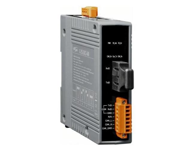
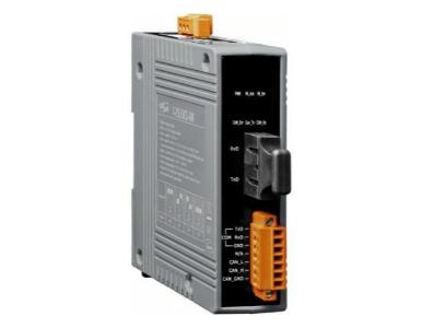
ICP DAS I-2533CS-60 - CAN to Single Mode Fiber Bridge / Converter- 1 (60 km) single mode, SC connector. Has operating temperatu by ICP DAS
|
|
|
|
I-2533CS-60_SUMMARY.html
- Fiber Type: SC ; Single mode ; 100 Base-FX
- Maximum transmission distance up 60km at any CAN baud rate
- NXP TJA1042 CAN transceiver
- 2500 Vrms isolation on the CAN side
- Supports both CAN 2.0A and CAN 2.0B
- Fully compatible with the ISO 11898-2 standard
- Rotary switch for CAN baud rate configuration
- Build-in switch for 120 O terminator resistor
- Removable terminal block, Mount easily on DIN-Rail
- Allows user-defined CAN baud rate
- Fiber broken line detection
- Utility tool for CAN message filter configuration
- The CAN port with the same Group ID can communicate with each other
|
|
|
I-2533CS-60_DESCRIPTION.html
The I-2533CS-60 is a local CAN bridge used to establish a connection between two CAN bus system via single mode fiber optic transmission medium. In order to solve the problem between CAN and fiber transmission medium, the I-2533CS-60 device is specially designed for converting the electrical CAN bus signal to fiber optic cables. The I-2533CS-A/B supports Wavelength Division Multiplexing (WDM) technology so that only a single fiber cable is needed for transmitting bi-directional CAN data. As the I-2533CS-A and I-2533CS-B must be paired because of hardware limitations, this means that the cost of deploying fiber cable can be effectively reduced.
I-2533CS-60.html
| CAN Interface |
| Connector |
Screwed terminal block (CAN_GND, CAN_L, CAN_H) |
| Baud Rate (bps) |
10 k ~ 1 M |
| Transmission Distance (m) |
Depend on baud rate |
| Terminator Resistor |
Switch for 120O terminator resistor |
| Isolation |
3000 VDCfor DC-to-DC, 2500 Vrms for photo-couple |
| Specification |
ISO 11898-2, CAN 2.0A and CAN 2.0B |
| Fiber Interface |
| Type |
SC Duplex type ; Single mode ; 100 Base-FX |
| Wave Length (nm) |
1310 |
| Fiber Cable (µm) |
8.3/125, 8.7/125, 9/125 or 10/125 |
| Transmission Distance (km) |
60 (indicative only) |
| Min. TX Output (dBm) |
5 |
| Max. TX Output (dBm) |
0 |
| Max. RX Sensitivity (dBm) |
-35 |
| Max. RX Overload (dBm) |
-5 |
| Budget (dBm) |
30 |
| UART Interface |
| COM1 |
RS-232 (configuration only) |
| COM1 Connector |
Screwed terminal block (RXD, TXD, GND) |
| LED |
| Round LED |
PWR, FB_Ack, FB_Err, CAN_Err, CAN_Tx and CAN_Rx LEDs |
| Power |
| Power supply |
Unregulated +10 ~ +30 VDC |
| Protection |
Power reverse polarity protection, Over-voltage brown-out protection |
| Power Consumption |
0.125 @ 24VDC |
| Mechanism |
| Installation |
DIN-Rail |
| Dimensions |
33.0 mm x 126 mm x 101 mm (W x L x H) |
| Environment |
| Operating Temp. |
-25C ~ +75C (-13F ~ +167F) |
| Storage Temp. |
-30C ~ +80C (-22F ~ +176F) |
| Humidity |
10 ~ 90% RH, non-condensing |
| CAN
Baud rate [bit/sec] |
Ideal
Fiber Length [km] |
| 1M |
30 |
| 800K |
30 |
| 500K |
30 |
| 250K |
30 |
| 125K |
30 |
| 50K |
30 |
| 20K |
30 |
| 10K |
30 |
|
|
|
|