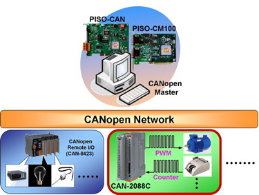
| CANopen Interface |
| NMT |
Slave |
| Error Control |
Node Guarding protocol / Heartbeat Producer |
| No. of PDOs |
10Rx , 10Tx |
| PDO Modes |
Event Triggered, Remotely requested, Cyclic and acyclic SYNC |
| PDO Mapping |
Available |
| No. of SDOs |
1 server, 0 client |
| Emergency Message |
yes |
| CANopen Version |
DS-301 v4.02 |
| Device Profile |
DSP-401 v2.1 |
| Specification |
ISO-11898-2, CAN 2.0A and CAN 2.0B |
Baud Rate (bps)
Setting by Rotary Switch |
10K, 20K, 50K, 125K, 250K, 500K, 800K, and 1M |
Node ID
Setting by Rotary Switch |
1 ~ 99 |
| Terminator Resistor |
Switch for 120 Ω terminator resistor |
| Connector |
5-pin screwed terminal block (CAN_GND, CAN_L, CAN_SHLD, CAN_H, CAN_V+) |
| EDS file |
Provide default EDS file |
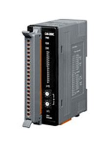
| LED |
PWR/RUN/ERR |
| PWM |
| Channels |
8 (Source) |
| Frequency |
0.2 Hz ~ 500 kHz (non-continuous) |
| Scaling Resolution |
16-bit (1 ~ 128 μs for each step) |
| Duty Cycle |
0.1 ~ 99.9 % |
| PWM Mode |
Burst mode, Continuous mode |
| Burst mode counter |
1~65535 counts |
| Trigger Mode |
Hardware (Start and Stop) or Software (Start and Stop) |
| Intra-module Isolation |
2500 Vrms |
| ESD Protection |
4 kV Contact for each channel |
| Digital Input |
| Channels |
8 (Sink/Source) |
| ON Voltage Level |
+5.5 ~ +30 V |
| OFF Voltage Level |
<3.5 V |
| Counter Frequency |
500 kHz Max. |
| Max. Counts |
32-bits (4,294,967,295) |
| Input Impedance |
2.2 kΩ, 0.5 W |
| Intra-module Isolation |
2500 Vrms |
| ESD Protection |
4 kV Contact for each channel |
| LED |
| CANopen Status |
3 LEDs for PWR/RUN/ERR |
| Terminal Resister |
1 LED as Terminal Resister indicators |
| PWM LED |
8 LEDs as PWM Output indicators |
| DI LED |
8 LEDs as Digital Input indicators |
| Power |
| Power Supply |
Unregulated +10 ~ +30 VDC |
| Power Consumption |
2 W |
| Mechanism |
| Installation |
DIN-Rail |
| Dimensions |
32.3 mm x 99 mm x 77.5 mm ( W x L x H ) Detail |
| Environment |
| Operating Temp. |
-25 ~ +75 ℃ |
| Storage Temp. |
-30 ~ +80 ℃ |
| Humidity |
10 ~ 90% RH, non-condensing |