| Serial Interface |
| Interface 1 |
Ethernet |
| Connection method |
IDC connection |
| Transmission length |
100 m (including patch cables) |
| Conductor cross section solid min. |
0.14 mm² |
| Conductor cross section solid max. |
0.34 mm² |
| Conductor cross section flexible min. |
0.14 mm² |
| Conductor cross section flexible max. |
0.34 mm² |
| Conductor cross section AWG min. |
26 |
| Conductor cross section AWG max. |
22 |
| Torque |
|
| Stripping length |
|
| Pin assignment |
1:1 |
| Basic functions |
PSE/Midspan, compliant with IEEE 802.3af, at |
| Serial transmission speed |
10/100/1000 Mbps |
| Output nominal voltage |
54 V DC (PoE) |
| Output power |
30 W |
| Maximum output power |
40 W |
| Interface 2 |
Ethernet |
| Connection method |
RJ45 CAT5e |
| Wire diameter incl. insulation |
1.6 mm (Terminal block is tested with PVC insulation - other insulation materials available on request) |
| Ambient conditions |
| Ambient temperature (operation) |
-40 °C ... 75 °C |
Ambient temperature
(storage/
transport) |
-40 °C ... 85 °C |
| Permissible humidity (operation) |
10 % ... 95 % (non-condensing) |
| Altitude |
5000 m (For restrictions see manufacturer's declaration) |
| Degree of protection |
IP20 (Manufacturer's declaration) |
| General |
| Electrical isolation |
VCC // SCM + FE // PoE |
| Test voltage data interface/power supply |
1.5 kV AC (50 Hz, 1 min.) |
| Electromagnetic compatibility |
Conformance with EMC Directive 2014/30/EU |
| Mounting position |
Vertical |
| Net weight |
324.72 g |
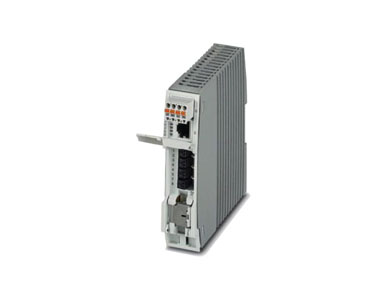
| Housing material |
Plastic |
| Color |
Gray |
MTTF
(SN 29500 standard, temperature 25 °C, operating cycle 21 % (5 days a week, 8 hours a day)) |
1510 Years |
MTTF
(SN 29500 standard, temperature 40 °C, operating cycle 34.25 % (5 days a week, 12 hours a day)) |
661 Years |
MTTF
(SN 29500 standard, temperature 40 °C, operating cycle 100 % (7 days a week, 24 hours a day)) |
256 Years |
| Conformance |
CE-compliant |
| UL, USA |
UL 60079-0 Ed. 6 / UL 60079-15 Ed. 4 |
| UL, USA/Canada |
Class I, Zone 2, AEx nA IIC T4, Ex nA IIC Gc X T4 |
| Class I, Division 2, Groups A, B, C, D |
| UL, Canada |
CSA 22.2 No. 60079-0 Ed. 3 / CSA 22.2 No. 60079-15:16 |
| Standards and Regulations |
| Electromagnetic compatibility |
Conformance with EMC Directive 2014/30/EU |
| Type of test |
Vibration resistance in acc. with EN 60068-2-6/IEC 60068-2-6 |
| Test result |
10 Hz ... 57 Hz, amplitude ±3.5 mm, 57 Hz ... 150 Hz, 5g |
| Type of test |
Shock in acc. with EN 60068-2-27/IEC 60068-2-27 |
| Test result |
30g for 11 ms, three shocks in each spatial direction |
| Type of test |
Continuous shock according to EN 60068-2-27/IEC 60068-2-27 |
| Test result |
10g for 16 ms, 1000 shocks in each spatial direction |
Standards/
regulations |
EN 61000-4-2 |
| Contact discharge |
± 6 kV (Test Level 3) |
| Indirect discharge |
± 6 kV |
Standards/
regulations |
EN 61000-4-3 |
| Frequency range |
80 MHz ... 3 GHz (Test Level 3) |
Standards/
regulations |
EN 61000-4-4 |
| Comments |
Criterion B |
Standards/
regulations |
EN 61000-4-5 |
| Signal |
± 1 kV (Data line, asymmetrical) |
| ± 2 kV (I/O cable on field side only, asymmetric) |
Standards/
regulations |
EN 61000-4-6 |
| Frequency range |
0.15 MHz ... 80 MHz |
Standards/
regulations |
IEC 61643-21 |
| IEC test classification |
C2 |
| Conformance |
CE-compliant |
| UL, USA |
UL 60079-0 Ed. 6 / UL 60079-15 Ed. 4 |
| UL, USA/Canada |
Class I, Zone 2, AEx nA IIC T4, Ex nA IIC Gc X T4 |
| Class I, Division 2, Groups A, B, C, D |
| UL, Canada |
CSA 22.2 No. 60079-0 Ed. 3 / CSA 22.2 No. 60079-15:16 |
| Noxious gas test |
ISA-S71.04-1985 G3 Harsh Group A |
| Function |
| Designation |
Shield current monitoring |
| Switch-on threshold |
≥ 30 mA |
| Local diagnostics |
Yellow LED |
| Precision |
± 5 % |
| Response time |
3 s |
| Continuous shield current |
≤ 2 A |
| Power consumption |
270 mW (Shield current monitoring) |
| Dimensions |
| Width |
30.2 mm |
| Height |
130 mm |
| Depth |
120 mm |
| Note |
| Utilization restriction |
EMC: class A product, see manufacturer's declaration in the download area |
| Power Supply |
| Nominal supply voltage |
24 V DC |
| 48 V DC |
| Supply voltage range |
18 V DC ... 57 V DC |
| Max. current consumption |
2.1 A |
| 1.4 A (24 V DC) |
| 0.7 A (48 V DC) |
| Power consumption |
≤ 75 W |
| Protective circuit |
Reverse polarity protection |
| Conductor cross section flexible max. |
4.00 mm² |
| Conductor cross section flexible min. |
0.75 mm² |
| Conductor cross section solid max. |
4.00 mm² |
| Conductor cross section solid min. |
0.75 mm² |
| Conductor cross section AWG max. |
12 |
| Conductor cross section AWG min. |
20 |
| Approvals |
| |
- cULus Listed
- cUL Listed
- UL Listed
|
| Environmental Product Compliance |
| REACH SVHC |
Lead 7439-92-1 |
| China RoHS |
Environmentally friendly use period: unlimited = EFUP-e |