| Models |
Regular version |
μPAC-5007
μPAC-5007P |
μPAC-5107
μPAC-5107P |
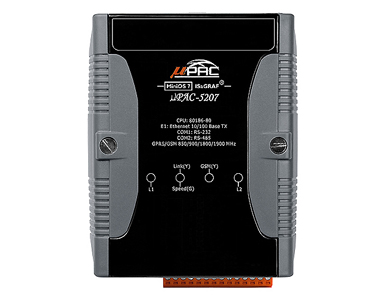
μPAC-5207 |
μPAC-5307 |
| PoE version |
| System Software |
|
| OS |
MiniOS7 |
| Development Software |
|
| ISaGRAF Version 3 |
IEC61131-3 standard. Languages: LD, ST, FBD, SFC, IL & FC |
| Max. Code Size |
Accepts max. 64 KB ISaGRAF code size (Appli.x8m must < 64 KB) |
| Power Supply |
|
| Protection |
Power reverse polarity protection |
| Frame Ground |
Yes (for ESD Protection) |
| Redundant Power Inputs |
Yes |
| Input Range |
+12 ~ +48 VDC |
| Power over Ethernet |
IEEE 802.3af, Class 1 (for PoE version) |
- |
| Power Consumption |
2 W ; μPAC-5x07D/5x07PD: 2.5 W |
| General Environment |
|
| Temperature |
Operating: -25 ~ +75 °C,
Storage : -30 ~ +80 °C |
| Humidity |
10 ~ 90 % RH (non-condensing ) |
| System |
|
| CPU |
80186 or compatible (16-bit and 80 MHz) |
| Watchdog Timer |
Yes, default 0.8 second |
| RTC (Real Time Clock) |
Provide second, minute, hour, date, day of week, month, year |
| SRAM |
768 KB |
| Battery Backup SRAM |
512 KB (Data valid up to 5 years, max. 1024 retain variables). |
| FLASH |
512 KB (100,000 erase/write cycles). |
| microSD Expansion |
Yes (ISaGRAF doesn’t support). |
| NVRAM |
31 bytes (Battery backup, data valid up to 10 years). |
| EEPROM |
16 KB (Retention > 100 years; 1,000,000 erase/write cycles). |
| 7-Seg. LED Display |
5-Digit 7-Seg. LED on the front of μPAC-5x07(D)/5x07P(D). It can display message and value. |
| NET ID |
User-assigned by software, 1 ~ 255 |
| Hardware Serial Number |
Yes, 64-bit hardware unique serial number. |
| Communication Interface |
|
| COM1 |
RS-232: TxD, RxD, RTS, CTS, GND, Non-Isolated.
Baudrate: Max. 115200 bps, Program downloads port. |
| COM2 |
RS-485: D2+, D2-, Non-Isolated, self-tuner ASIC inside.
Baudrate: Max. 115200 bps. |
| Ethernet |
RJ-45 x 1, 10/100 Base-TX, Program downloads port.
(Auto-negotiating, Auto MDI/MDI-X, LED indicator) |
| LED Indicator |
|
| Programmable LED |
2 (for User-Defined) |
| Hardware Expansion |
|
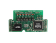
| I/O Expansion Bus |
Yes (for one XW-board). |
| Dimensions |
|
| W x H x D |
91 mm x 123 mm x 52 mm |
| PWM Output |
|
| Pulse Width Modulation Output |
All XW-series DO boards support PWM output. Max. 8 channels for one controller.
500 Hz max. for Off = 1 & On = 1 ms
Output square wave: Off: 1 ~ 32767 ms, On: 1 ~ 32767 ms |
| Counters |
|
| Parallel DI Counter |
All XW-series DI boards support DI counter.
Max. 8 channels for one controller. Counter value: 32-bit
500 Hz max. Min. ON & OFF width must > 1 ms |
| Remote DI Counter |
All remote I-7000 & I-87K DI modules support counters. 100 Hz max. value: 0 ~ 65535 |
| Remote High Speed Counter |
Optional I-87082: 100 kHz max. ,32-bit |
| Protocols |
|
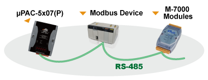
| Modbus RTU/ASCII Master Protocol |
Up to 2 COM Ports (COM1, COM2 and COM3-in-XW-Board) support Modbus RTU/ASCII Master protocol to connect to other Modbus Slave I/O devices. Max. Mbus_xxx Function Block amount:128. |
Modbus RTU Slave
Protocol |
Up to 2 COM Ports (COM1 and one of COM2/COM3-in-XW-Board) can support Modbus RTU Slave protocol for connecting ISaGRAF, PC/HMI/OPC Server & MMI panels. |
Modbus TCP/IP
Protocol |
Ethernet port supports Modbus TCP/IP Slave protocol for connecting ISaGRAF & PC/HMI. Max. 6connections. |
| Remote I/O |
One of COM2 or (COM3: RS-485 in-XW-Board) supports I-7K, I-87K I/O modules as Remote I/O.
I-87K series must plug on RU-87P (High profile) or I-87K (Low profile) I/O Unit. Max. 64 I/O modules for one PAC. |
| Fbus |
Built-in COM2 Port to exchange data between ICP DAS's ISaGRAF PACs. |
| Ebus |
To exchange data between ICP DAS's ISaGRAF Ethernet PACs via Ethernet port. |
| Send Email |
Actively or passively sending E-mail via Ethernet port through internet. Max.10 receivers for each sending and can send E-mail with an attached file. (Max. file size is about 488 KB) |
SMS:
Short Message Service |
One of (COM1 or COM3: RS-232 in-XW-Board) can link to a GSM modem to support SMS. User can request data/control the controller by cellular phone. The controller can also send data & alarms to user's cellular phone. Optional GSM modem: GTM-201-RS232 (GSM/GPRS 850/900/1800/1900)
Note: μPAC-5207, 5307 has built-in GPRS, no external GSM/GPRS modem required. |
| User-defined Protocol |
User can write his own protocol applied at COM1, COM2 & (COM3 ~ COM8 -in-XW-Board) by serial communication function blocks. |
| MMICON/LCD |
One of (COM3: RS-232 in-XW-Board) supports ICP DAS's MMICON. The MMICON is featured with a 240 x 64 dot LCD and a 4 x 4 Keyboard. User can use it to display picture, string, integer, float, and input a character, string, integer and float. |
| Redundancy Solution |
Two PACs plug with XW107 in slot0. One is Master, one is Slave. Master handles all inputs & outputs at run time. If Master is damaged (or power off), Slave will take over the control of Bus7000b. If Master is alive from damaged (or power up again), it takes the control of Bus7000b again. The change over time is about 5 seconds. Control data is exchanging via Ebus (if using a cross cable, no require any Ethernet Switch). All I/O should be RS-485 I/O except the status I/O in the slot 0: XW107. |
| CAN/CANopen |
Use COM1 or COM3 ~ COM8 (at the XW5xx RS-232 X-board) to connect one I-7530: the RS-232 to CAN converter to support CAN/CANopen devices and sensors. One PAC supports max. 3 RS-232 ports to connect max. 3 I-7530 modules. |